Logic gates and logic circuits
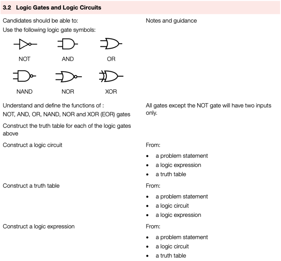
Logic gates
- Electronic circuits in computers, many memories and controlling devices are made up of thousands of logic gates.
- Logic gates take binary inputs and produce a binary output.
- Several logic gates combined together form a logic circuit and these circuits are designed to carry out a specific function.
- The checking of the output from a logic gate or logic circuit can be done using a truth table.
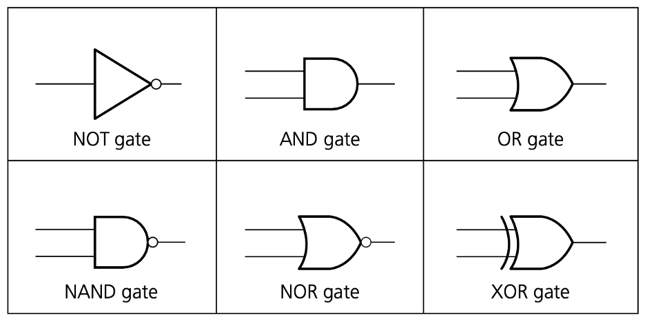
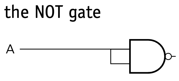
NOT gate
Description
- The output, X, is 1 if the input A is NOT 1
How to write this
- X = NOT A (logic notation)
(Boolean algebra)
Truth table
| Input | Output |
|---|---|
| A | X |
| 0 | 1 |
| 1 | 0 |
AND gate
Description
- The output, X, is 1 if input A is 1 and input B is 1
How to write this
- X = A AND B (logic notation)
(Boolean algebra)
Truth table
| Input | Input | Output |
|---|---|---|
| A | B | X |
| 0 | 0 | 0 |
| 0 | 1 | 0 |
| 1 | 0 | 0 |
| 1 | 1 | 1 |
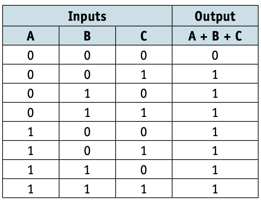
OR gate
Description
- The output, X, is 1 if input A is 1 or input B is 1.
How to write this
X = A OR B (logic notation)
(Boolean algebra)
Truth table
| Input | Input | Output |
|---|---|---|
| A | B | X |
| 0 | 0 | 0 |
| 0 | 1 | 1 |
| 1 | 0 | 1 |
| 1 | 1 | 1 |
NAND gate
Description
- The output, X, is 1 if input A is NOT 1 or input B is NOT 1.
How to write this
X = A NAND B (logic notation)
(Boolean algebra)
Truth table
| Input | Input | Output |
|---|---|---|
| A | B | X |
| 0 | 0 | 1 |
| 0 | 1 | 1 |
| 1 | 0 | 1 |
| 1 | 1 | 0 |
NOR gate
Description
- The output, X, is 1 if: input A is NOT 1 and input B is NOT 1
How to write this
X = A NOR B (logic notation)
(Boolean algebra)
Truth table
| Input | Input | Output |
|---|---|---|
| A | B | X |
| 0 | 0 | 1 |
| 0 | 1 | 0 |
| 1 | 0 | 0 |
| 1 | 1 | 0 |
XOR gate
Description
- The output, X, is 1 if (input A is 1 AND input B is NOT 1) OR (input A is NOT 1 AND input B is 1)
How to write this
- X = A XOR B (logic notation)
(Boolean algebra)
(Note: this is sometimes written as:
Truth table
| Input | Input | Output |
|---|---|---|
| A | B | X |
| 0 | 0 | 0 |
| 0 | 1 | 1 |
| 1 | 0 | 1 |
| 1 | 1 | 0 |
Logic circuits 1
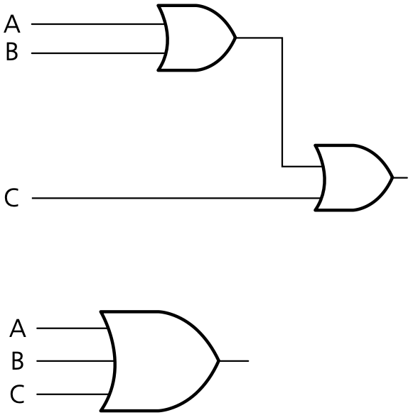
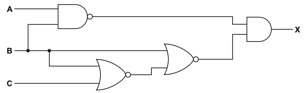
- Produce a truth table for the following logic circuit
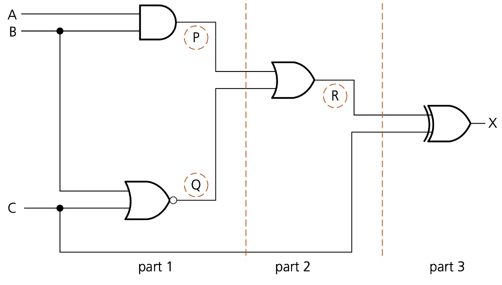
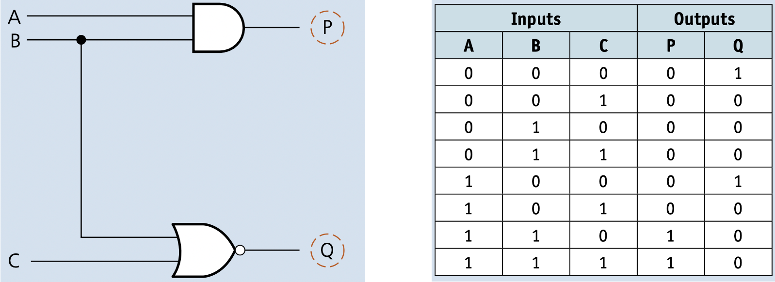
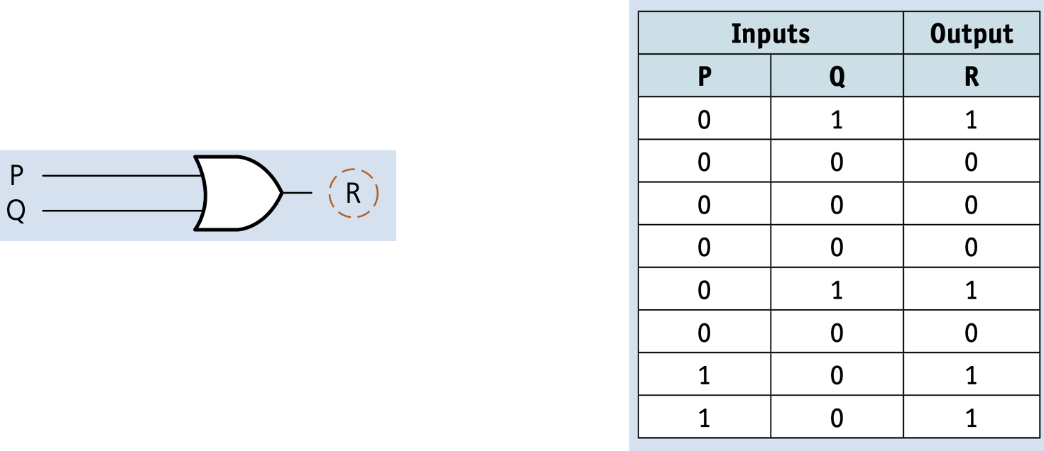
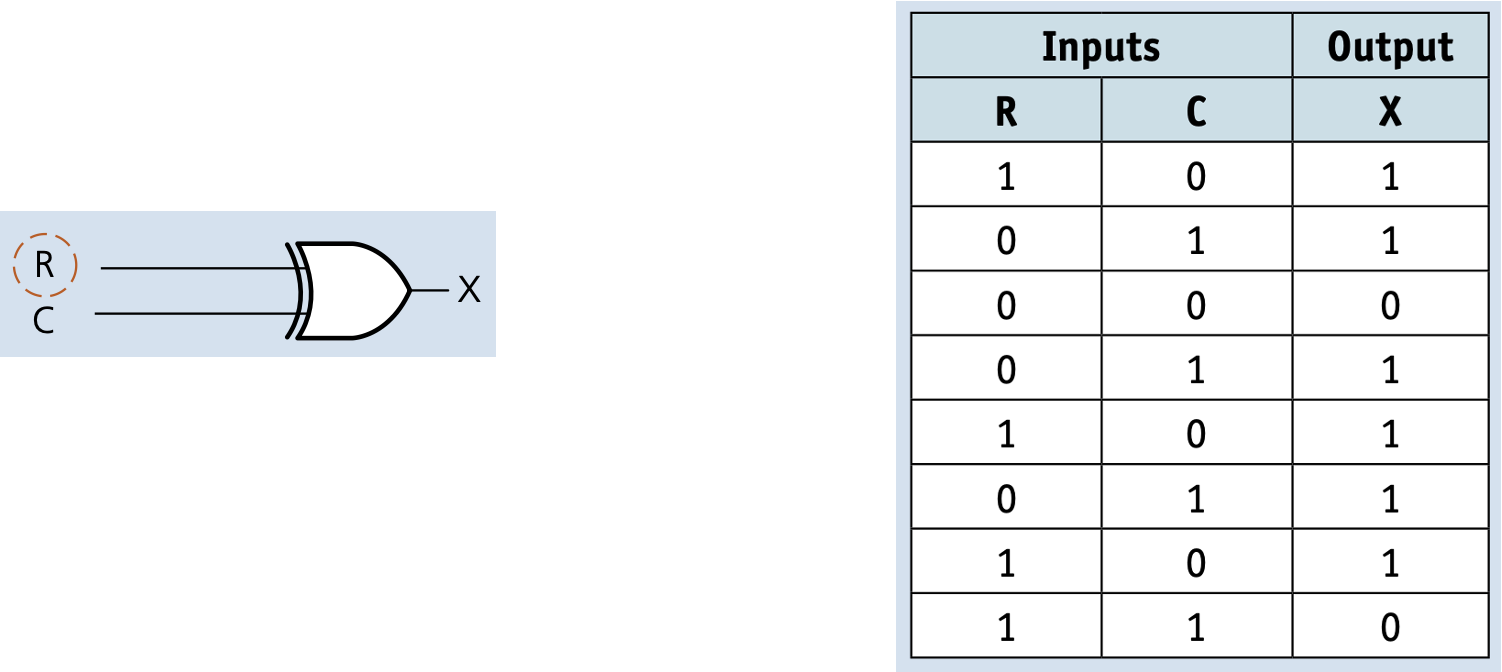
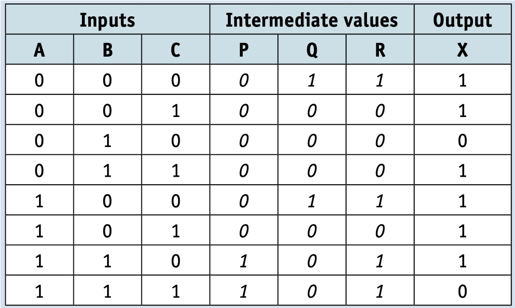
Hardware
Complete the truth table for the logic circuit.
| A | B | C | X |
|---|---|---|---|
| 0 | 0 | 0 | |
| 0 | 0 | 1 | |
| 0 | 1 | 0 | |
| 0 | 1 | 1 | |
| 1 | 0 | 0 | |
| 1 | 0 | 1 | |
| 1 | 1 | 0 | |
| 1 | 1 | 1 |
Logic circuits 2
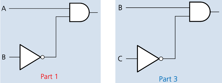
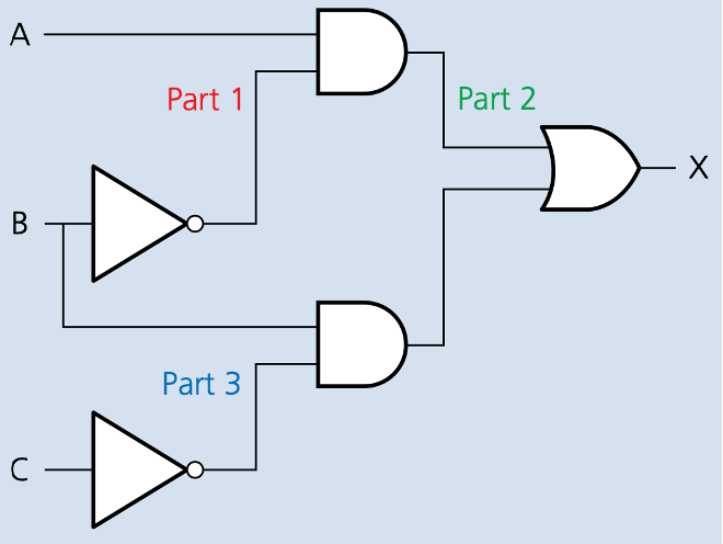
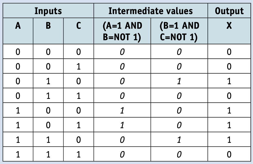
- A safety system uses three inputs to a logic circuit. An alarm, X, sounds if input A represents ON and input B represents OFF, or if input B represents ON and input C represents OFF.
- Produce a logic circuit and truth table to show the conditions which cause the output X to be 1.
Logic statement
X = 1 if (A = 1 AND B = NOT 1) OR (B = 1 AND C = NOT 1) this equates to A is ON and B is OFF
this equates to B is ON AND C is OFF
Boolean algebra
Hardware
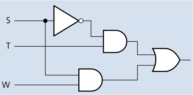
Draw the logic circuit for the logic expression:
X = (A AND B) OR (NOT ((A AND C) AND (B OR C))).
Logic circuits 3
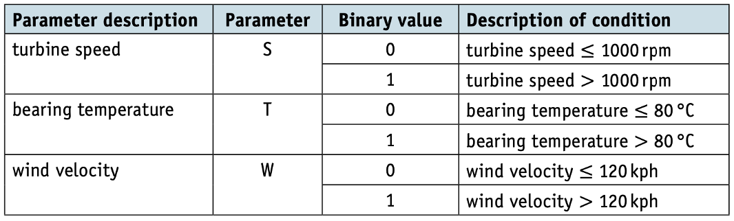
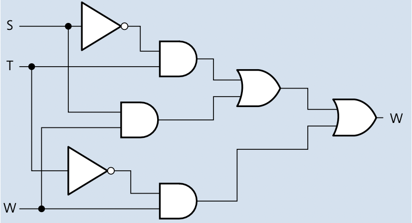
- A wind turbine has a safety system which uses three inputs to a logic circuit. A certain combination of conditions results in an output, X, from the logic circuit being equal to 1. When the value of X = 1, the wind turbine is shut down.
- The following table shows which parameters are being monitored and form the three inputs to the logic circuit.
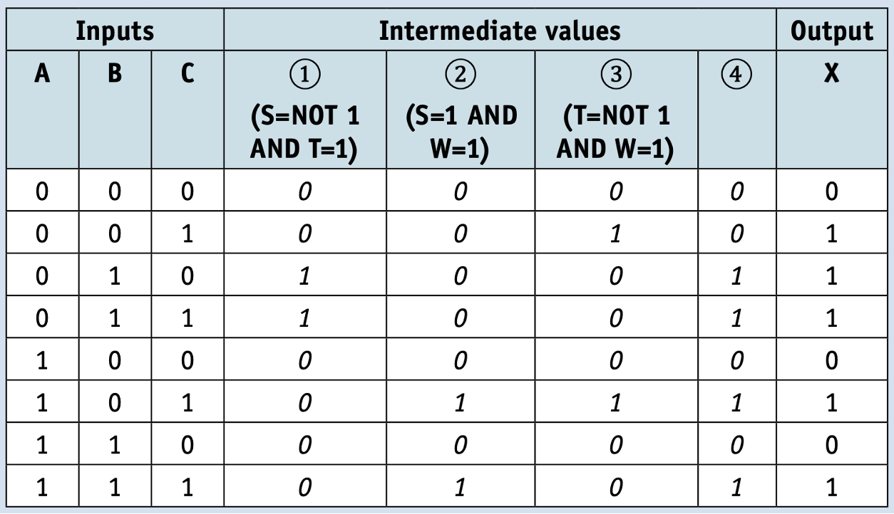
- The output, X, will have a value of 1 if any of the following combination of conditions occur:
- either turbine speed ≤ 1000 rpm and bearing temperature > 80 °C
- or turbine speed > 1000 rpm and wind velocity > 120 kph
- or bearing temperature ≤ 80 °C and wind velocity > 120 kph
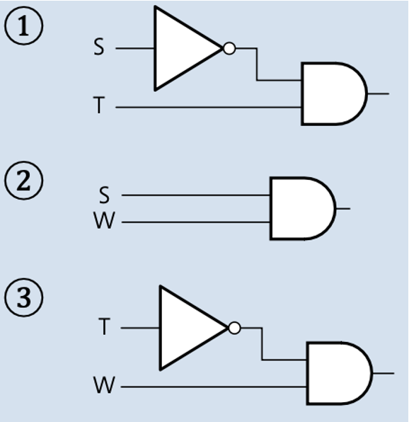
TIP
turbine speed 1000 rpm and bearing temperature > 80 °C logic statement:
(S = NOT 1 AND T = 1)
turbine speed > 1000 rpm and wind velocity > 120 kph logic statement:
(S = 1 AND W = 1)
bearing temperature 80 °C and wind velocity > 120 kph logic statement:
(T = NOT 1 AND W = 1)
Logic circuits in the real world
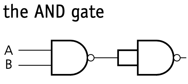
AND gate
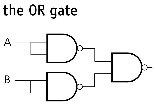
OR gate
NOT gate
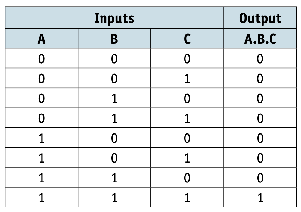
Multi-input logic gates
Multi-input AND gates
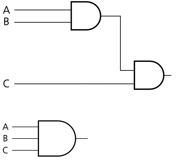
Multi-input OR gates